In any fluid conveyance system, from industrial processing plants to residential plumbing, the prevention of backflow is a critical operational and safety requirement. Check valves, also known as non-return valves, serve this fundamental purpose by permitting unidirectional flow and automatically preventing its reversal. The consequences of improper valve selection or failure can be severe, ranging from equipment damage and system contamination to significant operational inefficiencies. Therefore, understanding the nuanced performance characteristics and application-specific requirements of these components is paramount for ensuring system integrity and reliability.
This comprehensive review and buying guide is designed to demystify the selection process by providing an in-depth analysis of the industry’s top-performing models. Navigating the diverse market to find the optimal solution can be a complex undertaking, but by examining key criteria such as material compatibility, pressure ratings, and valve type, our goal is to help you identify the best check valves for your unique needs. The following sections offer detailed evaluations and a structured framework to empower engineers, technicians, and consumers to make an informed and effective purchasing decision.
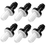
We will discuss the best check valves further down, but for now, consider checking out these related items on Amazon:


Last update on 2026-03-23 / Affiliate links / #ad / Images from Amazon Product Advertising API
An Analytical Overview of the Check Valve Market
Check valves, or non-return valves, are fundamental components in nearly every fluid-handling system, designed for the singular purpose of preventing reverse flow. The global market for these devices is experiencing robust growth, with analysts projecting a compound annual growth rate (CAGR) of over 4.5% through 2028. This expansion is primarily fueled by escalating industrialization, significant investments in water and wastewater infrastructure, and the continued growth of the oil & gas, chemical processing, and power generation industries. As systems become more complex and operational demands intensify, the need for reliable, automatic flow control to protect equipment and maintain process integrity has made the check valve an indispensable, high-demand component.
The core benefits of employing check valves extend far beyond simply stopping backflow. Their primary value lies in safeguarding critical and expensive upstream equipment, such as pumps and compressors, from damage caused by reverse flow and the associated water hammer effect. This protective function is crucial for preventing costly operational downtime and extending the service life of system components. Furthermore, check valves are vital for preventing cross-contamination between different fluid lines, maintaining system pressure, and eliminating the possibility of siphonage. By doing so, they enhance overall system safety, efficiency, and reliability with a simple, passive mechanical design that requires no external power or control.
Despite their simple function, check valves present significant engineering challenges, primarily centered on proper selection and application. Issues such as water hammer, valve chatter, excessive pressure drop, and premature failure due to sticking or leaking are common problems that stem from incorrect specifications. The challenge of identifying the best check valves for a given service requires a thorough analysis of fluid characteristics, operating pressures, temperatures, and flow dynamics. A failure to properly match the valve type—be it swing, lift, ball, or diaphragm—to the specific application can result in severe energy losses, compromised system performance, and even catastrophic equipment failure.
Looking ahead, the evolution of check valve technology is focused on addressing these longstanding challenges through innovation in design and materials. The industry is moving towards more efficient, non-slam designs that minimize pressure loss and mitigate water hammer. There is also a growing trend in the development of “smart” check valves embedded with sensors to monitor performance and enable predictive maintenance, aligning with the broader Industry 4.0 shift. Concurrently, advancements in material science are yielding valves capable of withstanding more extreme corrosive and high-temperature environments, ensuring their continued relevance and critical role in future industrial applications.
Top 5 Best Check Valves
Val-Matic Silent Check Valve
The Val-Matic Silent Check Valve is a center-guided, spring-assisted, globe-style non-slam check valve. Its construction typically involves a ductile or cast iron body with options for bronze or stainless steel trim, providing durability for a range of water and industrial fluid applications. The core design feature is a fully guided disc with a calibrated spring, which initiates closure as forward flow decelerates, prior to flow reversal. This preemptive action is engineered to prevent the pressure surge and hydraulic shock known as water hammer. Available in a wide array of sizes and pressure classes (e.g., ANSI Class 125/250), its globe-style body, while requiring more installation space than a wafer valve, facilitates a stable and controlled flow path around the disc assembly.
From a performance standpoint, the valve’s primary metric of success is the quantifiable reduction of water hammer, protecting pumps, piping, and other system components from damaging pressure spikes. The spring-assisted mechanism ensures a rapid yet controlled closure that is independent of gravity or installation orientation. This reliability comes at the cost of a higher pressure drop (head loss) compared to full-port swing check valves, a necessary trade-off for its non-slam characteristics. The value proposition is highest in critical applications where system longevity and protection against hydraulic shock are paramount, such as high-rise building booster systems or municipal water distribution networks. Its robust build and field-serviceable design contribute to a low total cost of ownership in these demanding environments.
Flomatic Model 408S6 Swing Check Valve
The Flomatic Model 408S6 is a heavy-duty, iron-body swing check valve designed with flanged connections conforming to ANSI B16.1 standards. Its fundamental components include an ASTM A126 Class B cast iron body and a bronze-mounted clapper that swings on a bronze hinge pin, providing a durable bronze-to-bronze seating arrangement. The design is characterized by a full-port, unobstructed flow path when the valve is fully open, which is a critical feature for minimizing hydraulic resistance. Intended for municipal water, wastewater, and general industrial services, it is typically rated for pressures up to 200 PSI CWP and can be equipped with an external lever and weight or spring to assist in closure and prevent clapper slam in certain conditions.
In terms of performance, the principal advantage of the Model 408S6 is its exceptionally low head loss, which translates to higher system efficiency and lower energy consumption for pumping. The full-port design yields a high flow coefficient (Cv) relative to other valve types. Positive sealing is achieved via the seating of the clapper under backpressure. However, in systems with high flow velocities or abrupt pump shutdowns, a standard swing check can be susceptible to significant water hammer as the clapper slams shut upon flow reversal. The value of this valve is therefore maximized in applications like gravity-fed lines or constant-pressure systems where flow efficiency is the primary concern and the risk of hydraulic shock is inherently low or managed by other means. Its simple, robust construction ensures a long service life with minimal maintenance requirements.
Hayward TC Series True Union Ball Check Valve
The Hayward TC Series is a ball check valve constructed from thermoplastics, primarily PVC or CPVC, with elastomeric seats in EPDM or FKM. This material composition provides superior resistance to a wide range of corrosive chemicals, making it suitable for applications in chemical processing, water treatment, and aquaculture where metallic valves would degrade. The key structural feature is its true union design, which incorporates union nuts on both ends. This allows the central valve body to be easily removed from the pipeline for inspection, cleaning, or replacement without requiring the cutting or re-welding of pipe sections. The valve operates via a free-floating solid plastic ball that is pushed away from its seat by forward flow and returns to seal against the seat under backpressure and gravity.
Performance is contingent on proper installation and system dynamics. The valve provides a reliable, positive seal against backflow, even at very low backpressures, and can be installed either vertically (upward flow) or horizontally. Head loss is moderate and dependent on the degree to which the ball is lifted into the flow-through cavity. The design’s lack of mechanical components like springs or hinges enhances its reliability in an operational context, but it can be susceptible to ball chattering and wear in systems with pulsating flow. The primary value of the TC Series lies in its combination of corrosion resistance and serviceability. The true union feature significantly reduces system downtime and maintenance costs over the valve’s lifespan, offering a superior long-term investment for corrosive fluid handling systems.
DFT Model SCV Check Valve
The DFT Model SCV is an in-line, spring-assisted, wafer-style check valve engineered for high-performance applications. Its defining feature is its compact, flange-less wafer body, which is designed to fit between mating pipe flanges, resulting in significant savings in weight, space, and installation time compared to full-bodied flanged valves. Material options are extensive, ranging from carbon steel and stainless steel to high-performance alloys like Hastelloy, allowing for precise matching to process fluid compatibility and temperature requirements. The internal mechanism consists of a center-guided disc and a custom-calibrated spring, which provide a stable, axial flow path and enable precise control over the cracking pressure needed to open the valve.
The performance of the SCV is characterized by its reliable, non-slam closure. The spring-assisted design ensures the disc begins to close as flow decelerates, seating the valve securely at the moment of zero flow velocity, thereby preventing flow reversal and the associated water hammer. This functionality is consistent across all installation orientations. While its head loss is greater than that of a full-port swing check, it is generally lower than that of a globe-style silent check valve, offering a balance between non-slam performance and flow efficiency. The value of the DFT SCV is most evident in industrial, chemical, and HVAC systems where space is at a premium and the prevention of hydraulic shock is critical for protecting sensitive equipment. Its engineered design and material versatility justify its position as a premium solution for demanding process control.
Zoeller 30-0181 Sump Pump Check Valve
The Zoeller 30-0181 is a check valve specifically designed and sized for residential and light commercial sump pump discharge lines. The body is constructed of durable, corrosion-proof Acrylonitrile Butadiene Styrene (ABS). It utilizes a full-flow design with an internal flapper made from flexible, long-lasting nitrile rubber to handle the intermittent flow and potential small debris found in sump water. A key feature is its user-friendly connection system, which incorporates flexible rubber unions with stainless steel hose clamps to accommodate either 1-1/4″ or 1-1/2″ PVC or ABS pipe. This solvent-free connection method allows for rapid installation, removal, and re-installation without specialized tools or adhesives.
In performance, the valve is optimized for low-pressure, high-flow-rate applications typical of sump pumps. The full-flow design minimizes friction loss in the discharge line, ensuring the pump operates close to its maximum rated capacity and reducing overall run time. The nitrile flapper creates a positive seal against backflow when the pump deactivates, preventing water in the discharge pipe from draining back into the sump pit. This action reduces the frequency of pump cycling, thereby extending motor life and lowering energy consumption. While the closure can produce an audible “thud,” this is generally considered acceptable for its utility application. The valve’s value proposition is exceptionally high for its intended purpose, providing a reliable, inexpensive, and easily serviceable solution that is critical for the proper and efficient operation of a basement dewatering system.
The Unseen Guardian: Why Every Fluid System Needs a Check Valve
Check valves are essential safety devices purchased to solve a single, critical problem: backflow. In any system involving the movement of liquids or gases, flow is intended to go in only one direction. Backflow, the reversal of this intended direction, can lead to catastrophic consequences. It can cause cross-contamination of potable water supplies with non-potable water, damage expensive equipment like pumps and compressors by forcing them to run backward, or disrupt sensitive chemical processes. A check valve acts as an automatic, one-way gate, allowing fluid to pass forward but snapping shut to prevent any reverse movement. This simple, passive function is fundamental to maintaining system integrity, safety, and operational control, making the purchase of a check valve a non-negotiable requirement for responsible system design and operation.
From a practical standpoint, the need for the best check valves is driven by reliability and performance requirements. Not all check valves are created equal, and the selection of a superior model is crucial for mission-critical applications. Factors such as the valve’s cracking pressure (the minimum upstream pressure at which the valve will operate), its sealing capability, and its response time are paramount. Furthermore, the materials of construction must be compatible with the fluid being handled—be it corrosive chemicals, high-temperature steam, or abrasive slurries—to prevent degradation and failure. A high-quality valve is engineered to withstand specific system pressures and temperatures without failing, ensuring it performs its protective function reliably over thousands of cycles. Opting for the best available valve is a practical decision to guarantee operational safety and prevent the very failures it is installed to stop.
The economic factors compelling the purchase of high-performance check valves are centered on risk mitigation and total cost of ownership. While a premium check valve may have a higher initial purchase price, this cost is minimal when compared to the potential financial devastation of a backflow incident. The economic fallout from a single failure can include exorbitant repair or replacement costs for primary equipment, lost revenue from system downtime and spoiled product, and potential legal liability or regulatory fines in cases of environmental contamination or public health risks. A durable, well-made check valve minimizes these risks, offering a significantly lower total cost of ownership through its longevity, reduced maintenance needs, and the prevention of costly catastrophic events. This makes investing in the best valve a sound financial strategy.
Ultimately, the practical and economic arguments converge, framing the purchase of the best check valves as a strategic investment in operational resilience. The practical need for a reliable, correctly specified valve that guarantees system safety directly supports the economic imperative to protect valuable assets and maintain profitability. A substandard valve is a latent liability, a point of failure waiting to happen, whereas a high-quality valve is a form of insurance. Therefore, the decision is not merely about stopping reverse flow; it is about proactively managing risk, ensuring process stability, and safeguarding the long-term financial health of an operation. In this context, the best check valve is not an expense but an essential component for secure, efficient, and profitable system management.
Strategic Installation and Placement Considerations
The performance of even the highest-quality check valve is fundamentally tied to its proper installation and strategic placement within a fluid system. A common mistake is to view installation as a mere matter of connecting the valve into a pipeline. However, its position relative to other components like pumps, elbows, and control valves is critical. For instance, most check valves have a required flow direction, clearly marked by an arrow on the valve body, which must be strictly observed. Furthermore, the orientation of the valve—whether it is installed in a horizontal or vertical line—can significantly impact its function. Some designs, like a basic swing check valve, rely on gravity to help close the flapper and may not function correctly or at all in a vertical line with upward flow unless specifically designed for it.
In sump pump and ejector pump applications, the check valve’s placement is paramount for protecting the pump and preventing short-cycling. The valve should be installed on the vertical discharge pipe, typically above the pit cover, to allow for easy access for inspection and service. Its primary role here is to prevent the entire volume of water in the discharge pipe from flowing back into the sump pit after the pump shuts off. Without it, the pump would be forced to re-pump the same water, leading to excessive wear on the motor and switches, as well as wasted electricity. Proper placement ensures that the pump motor is protected from the backpressure and water hammer that can occur when the column of water abruptly stops and reverses direction.
For private well water systems, the check valve serves a slightly different but equally vital purpose. Often, a check valve is integrated into the submersible pump itself, but an additional valve is typically installed in the pipe just before the pressure tank. This placement is crucial for maintaining pressure within the system. When the pump turns off after reaching the cut-out pressure, the check valve prevents water from draining back down into the well. If this backflow were to occur, the system pressure would drop rapidly, causing the pressure switch to immediately call for the pump to turn on again. This rapid, unnecessary cycling is a leading cause of premature pump failure.
Beyond residential applications, industrial and commercial systems demand even more precise placement considerations. Fluid turbulence is a major enemy of check valve longevity. Turbulence, often generated by pumps, elbows, or throttling valves, can cause the valve’s disc to flutter or vibrate rapidly. This leads to excessive wear on the hinge pin, disc, and seat, resulting in premature failure and leakage. To mitigate this, a common engineering guideline is to install the check valve a distance of at least five to ten pipe diameters downstream from any source of turbulence. This allows the flow profile to stabilize before it reaches the valve, ensuring smooth, predictable operation and maximizing the component’s service life.
Maintenance Protocols and Lifespan Maximization
A common misconception among homeowners and even some facility managers is that check valves are “fit and forget” components. In reality, they are active mechanical devices with moving parts that are subject to wear, corrosion, and fouling over time. Implementing a proactive maintenance schedule is the single most effective way to ensure the valve’s reliability and maximize its operational lifespan. Ignoring maintenance can lead to catastrophic failures, such as basement flooding from a failed sump pump valve or significant damage to expensive industrial equipment. A robust maintenance plan moves from a reactive, failure-based approach to a preventative strategy that upholds system integrity.
The first level of maintenance involves regular, non-invasive inspections. On a quarterly or semi-annual basis, a visual and auditory check should be performed. Visually inspect the valve body and its connections for any signs of weeping or active leaks, which could indicate a failing seal or a crack in the housing. Listen to the system as it operates. A properly functioning check valve should operate quietly. Any audible chattering, slamming, or thudding noises (a phenomenon known as water hammer) are immediate red flags. These sounds indicate that the valve disc is not being properly cushioned and is slamming shut, which can cause severe stress to the valve, pipes, and joints over time.
For serviceable check valves, a more thorough internal inspection and cleaning should be scheduled periodically, with the frequency determined by the application’s demands. In a critical or high-cycle application, this may be annually; for a residential sump pump, it might be every two to three years. This process involves isolating the valve from the system, depressurizing the line, and carefully disassembling the valve according to the manufacturer’s instructions. Once open, all internal components—such as the flapper, disc, spring, and seat—should be cleaned of any accumulated sediment, scale, or debris. This is also the time to inspect gaskets and seals for signs of brittleness, cracking, or deformation, replacing them as necessary.
Several environmental and operational factors directly influence a check valve’s lifespan and dictate the required maintenance intensity. The nature of the fluid medium is paramount; a valve handling clean, potable water will last significantly longer with less maintenance than one managing wastewater, chemical slurries, or water with high mineral content that can cause scale buildup. Furthermore, the frequency of cycles has a direct impact on wear. A valve in a constantly cycling system will experience more wear on its moving parts than one in a static or standby line. Understanding these factors allows for the creation of a tailored maintenance schedule that prevents unexpected failures and ensures the valve performs reliably for its intended service life.
Diagnosing Common Check Valve Failures and Issues
Understanding the symptoms of a failing check valve is crucial for timely diagnosis and repair, preventing minor issues from escalating into major system damage. Check valve failures generally fall into three categories: failure to seal completely (allowing backflow), failure to open (causing a blockage), and improper or noisy operation. Each of these symptoms points to specific underlying mechanical problems. The most common and often most damaging failure is the inability to create a tight seal when flow stops or reverses. This is the fundamental purpose of the valve, and its failure can have immediate and severe consequences for the system it is designed to protect.
One of the most telling signs of a check valve that is not sealing properly is the frequent or continuous cycling of a pump. In a sump pump system, if you hear the pump turn on for a short period, shut off, and then turn on again just a minute or two later without any new water entering the pit, the check valve is almost certainly leaking. The water in the discharge pipe is flowing back into the pit, raising the float switch and re-activating the pump. This issue is most often caused by a small piece of debris, such as grit or gravel, becoming lodged between the valve’s disc and its seat, preventing a complete closure. In other cases, the rubber seal or the valve seat itself may be worn out or degraded after years of service.
A loud banging, thumping, or chattering sound emanating from the pipeline when a pump shuts off is a classic symptom of water hammer, which is often caused or exacerbated by an incorrect or failing check valve. This occurs when the flow of water stops abruptly, causing the valve’s flapper or disc to slam shut with tremendous force. The resulting shockwave reverberates through the piping system. While some degree of noise can be normal with basic swing check valves, excessive slamming indicates a problem. This is often seen when a fast-closing valve is used in a high-velocity flow line. The violent closure not only creates noise but can also lead to pipe fatigue, joint failure, and damage to the valve’s internal components over time. Switching to a “silent” or spring-assisted check valve, which forces the disc to close more gently before flow reversal can occur, is often the solution.
Conversely, a complete or partial blockage of flow is a symptom of a check valve failing in the open or closed position. If a pump is running but there is little to no output, the check valve may be stuck shut. This can be caused by severe internal corrosion, a broken hinge or spring, or a large obstruction that has become permanently lodged in the valve. This is an extremely dangerous condition as it can cause the pump to overheat and burn out, or in a pressurized system, it can lead to a dangerous over-pressurization of the line upstream of the valve. A partial blockage, which manifests as reduced system performance, can be caused by a valve that is not opening fully due to similar issues, restricting the flow and reducing overall system efficiency.
Material Selection: Matching Valve Composition to Application Demands
Choosing the correct check valve material is not merely a question of budget but a critical engineering decision that directly impacts the safety, longevity, and compliance of a fluid handling system. While a basic buying guide may list common materials, a deeper analysis reveals that material selection is a complex interplay between fluid compatibility, operating temperature and pressure, and the specific demands of the application. An inappropriate material choice can lead to rapid corrosion, chemical leaching, mechanical failure, and ultimately, a complete compromise of the system the valve was meant to protect. Therefore, a thorough understanding of the primary material categories is essential for making an informed decision.
For many residential and light commercial applications, plastics like PVC (Polyvinyl Chloride) and CPVC (Chlorinated Polyvinyl Chloride) are a cost-effective and highly functional choice. PVC excels in applications involving cold water, such as sump pump discharge lines, irrigation, and pools, due to its complete immunity to rust and excellent resistance to corrosion from salts and mild acids. CPVC offers a similar profile but with a significantly higher temperature tolerance, making it suitable for hot water lines. The primary limitations of these plastics are their lower pressure ratings compared to metals and their susceptibility to degradation from UV radiation if used outdoors without protection. They are completely unsuitable for systems involving most hydrocarbons or solvents, which can cause the material to soften and fail.
Brass and bronze are the traditional materials of choice for potable water systems and general-purpose plumbing. As copper alloys, they offer a superb balance of mechanical strength, durability, and good corrosion resistance in most water conditions. They can handle significantly higher pressures and temperatures than plastics, making them ideal for boiler feeds, well water systems, and hot water recirculation lines. When selecting a brass valve for drinking water, it is legally required in many regions to use a “lead-free” alloy, which contains less than 0.25% lead, to prevent leaching into the water supply. While robust, standard brass can be susceptible to dezincification in highly chlorinated or soft water environments, which can weaken the valve over time.
For the most demanding industrial, chemical, or high-purity applications, stainless steel and ductile iron are the superior choices. Stainless steel, particularly grades 304 and 316, offers exceptional resistance to a wide spectrum of corrosive chemicals, as well as extreme temperatures, both high and low. This makes it the standard material for food and beverage processing, pharmaceuticals, and marine environments where saltwater corrosion is a major concern. Ductile iron is prized for its immense strength, pressure rating, and impact resistance, making it the workhorse for large-diameter municipal water and wastewater mains. While these materials represent a higher initial investment, their unparalleled durability and resistance to failure provide long-term value and safety in critical and harsh service environments.
Buying Guide: Selecting the Optimal Check Valve for Your Application
In the intricate world of fluid dynamics and process control, the check valve, also known as a non-return or one-way valve, serves a deceptively simple yet fundamentally critical function: to permit fluid flow in a single direction while automatically preventing reverse flow, or backflow. This unilateral control is paramount for protecting equipment, maintaining system pressure, preventing contamination, and ensuring the overall operational integrity of countless systems across residential, commercial, and industrial sectors. From safeguarding a home’s sump pump against backflow to protecting multi-million dollar industrial compressors from catastrophic damage, the role of the check valve is indispensable. However, the selection of an appropriate check valve is far from a one-size-fits-all proposition. The market offers a vast array of designs, materials, and operational mechanisms, each engineered for specific conditions. A valve that excels in a low-pressure, clean water application could fail catastrophically in a high-pressure, corrosive chemical line. Therefore, an analytical approach to selection, grounded in a thorough understanding of key performance parameters and system requirements, is essential. This guide will dissect the six most critical factors to consider when purchasing a check valve, moving beyond simple definitions to explore the practical impact and data-driven considerations that empower engineers, technicians, and facility managers to make an informed and optimal choice.
1. Valve Type and Mechanism
The most fundamental decision in selecting a check valve is its core design and operating mechanism, as this dictates its suitability for different media, flow conditions, and installation orientations. The primary types include Swing, Lift (Piston and Ball), Diaphragm, and Duckbill check valves. A Swing Check Valve operates with a disc, or flapper, that swings on a hinge to open with forward flow and swings closed against a seat to prevent backflow. They are common in full-flow applications where low pressure drop is critical. Lift Check Valves use a piston or ball that is lifted off its seat by the fluid’s pressure and velocity; gravity and/or a spring returns it to the seat when flow stops or reverses. These are often preferred for high-pressure service and in applications where prevention of valve “chatter” is important. Diaphragm valves use a flexible rubber diaphragm which flexes open under pressure and returns to a sealed position, making them ideal for low-pressure, high-purity, or corrosive applications.
The practical impact of this choice is significant. For instance, a standard swing check valve is highly effective for horizontal pipelines carrying clean liquids or gases, offering one of the lowest pressure drops of any check valve design. However, it is generally unsuitable for liquids containing significant solids or debris, as particles can prevent the flapper from seating properly, leading to leakage. Furthermore, in applications with pulsating flow, the flapper can continuously open and close (chatter), causing premature wear on the hinge pin and seat. In contrast, a ball check valve, with its simple, robust design, is often better suited for viscous fluids or slurries as the ball’s rolling motion helps to clear the seat of particulates. Data from fluid dynamic studies show that a full-port swing check can have a Flow Coefficient (Cv) value nearly as high as an equivalent length of straight pipe, while a lift check valve’s more tortuous flow path can result in a pressure drop that is three to four times higher for the same flow rate. This energy loss, while negligible in some systems, can translate to significant operational costs in large-scale, continuous-flow pumping applications.
2. Material Compatibility
The materials used for the valve body and its internal sealing components must be chemically compatible with the process fluid and resilient to the system’s operating temperature and pressure. Failure to select appropriate materials can lead to rapid corrosion, chemical degradation, contamination of the process media, and ultimately, catastrophic valve failure. Common body materials include plastics like PVC and CPVC, which are cost-effective and offer excellent resistance to water, salts, and many acids, but have strict temperature and pressure limitations. Metals such as Brass are durable and suitable for non-corrosive media like air, oil, and water in residential and light industrial settings. For more demanding applications, Stainless Steel (typically grades 304 and 316) provides superior corrosion resistance, with 316 Stainless Steel being the standard for marine environments, chlorides, and a wider range of chemicals. For large-diameter water or steam lines, Cast Iron and Ductile Iron are common due to their strength and cost-effectiveness.
The data-driven aspect of material selection involves cross-referencing fluid properties with material compatibility charts and pressure-temperature rating tables. For example, a PVC Sch 80 check valve may be rated for 235 PSI at 73°F (23°C), but its pressure rating dramatically de-rates to just 50 PSI at its maximum operating temperature of 140°F (60°C). In contrast, a 316 Stainless Steel valve of a similar class can maintain its pressure rating across a much wider temperature range, often exceeding 400°F (204°C). The seal material (elastomer) is equally critical. EPDM is excellent for water-based applications but fails quickly when exposed to petroleum products. Buna-N (Nitrile) is the go-to for oils and fuels but has poor resistance to ozone and UV light. Viton™ (FKM) offers broad chemical resistance and high-temperature performance but comes at a premium cost. A meticulous review of the fluid’s chemical composition, concentration, and temperature profile is non-negotiable to ensure long-term reliability and safety.
3. Cracking Pressure and Sealing Performance
Cracking pressure is the minimum amount of upstream pressure required to “crack” open the check valve and initiate flow. This is a critical parameter that directly impacts system responsiveness and efficiency. In applications such as low-pressure drainage or gravity-fed systems, a valve with a very low cracking pressure (e.g., 0.25 PSI or less) is essential to allow flow with minimal head. Conversely, in a system with constant pressure fluctuations, a higher cracking pressure (e.g., 1 to 5 PSI), often achieved with a spring-loaded mechanism, may be desirable to prevent the valve from opening and closing unnecessarily in response to minor system noise. This prevents valve chatter and associated wear. The choice directly affects whether the valve performs its function effectively or inadvertently becomes an obstruction in the system.
Sealing performance dictates the valve’s ability to prevent backflow once closed. The industry standard for leakage is often defined by standards like API 598, which specifies acceptable leakage rates for both metal-seated and resilient-seated (soft-seated) valves. A “bubble-tight” seal, which implies zero measurable leakage, is typically achieved with soft-seated valves (e.g., using EPDM or Viton™ seals) and is critical in applications involving hazardous gases, chemical dosing, or where any amount of backflow could cause contamination. Metal-to-metal seated valves, while more durable at extreme temperatures and pressures, may have a small, allowable leakage rate. For example, under API 598, a 2-inch metal-seated check valve might be permitted a leakage of 4 drops per minute for liquid service. Specifying a requirement for bubble-tight shutoff is essential for critical applications, while accepting a standard leakage rate may be sufficient and more cost-effective for general service.
4. Flow Characteristics (Cv) and Head Loss
The Flow Coefficient, or Cv, is a standardized measure of a valve’s efficiency in allowing fluid to flow through it. It is defined as the number of U.S. gallons per minute of water at 60°F that will flow through a fully open valve with a pressure drop of one pound per square inch (PSI). A higher Cv value indicates a lower resistance to flow and, consequently, a lower pressure drop (head loss) across the valve. This is a paramount consideration in system design, particularly in pumping systems, as excessive head loss forces the pump to work harder, consuming more energy and increasing operational costs over the life of the system. Choosing a valve with a high Cv is crucial for maximizing system efficiency and minimizing energy expenditure.
The data starkly differentiates valve types. For example, a 4-inch full-port swing check valve might have a Cv value of approximately 750, meaning it presents very little obstruction to flow. In contrast, a 4-inch spring-loaded silent check valve, with its more restrictive internal design, might have a Cv of around 450, and a globe-style lift check valve could be as low as 250. This means that at the same flow rate, the pressure drop across the lift check could be nearly three times higher than across the swing check. This difference in head loss can be calculated using the formula: Pressure Drop = (Flow Rate / Cv)². For a large industrial process running 24/7, even a 1-2 PSI difference in head loss can translate into thousands of dollars in additional annual energy costs. Therefore, analyzing the Cv ratings of potential valves and balancing flow efficiency against other requirements like sealing performance and water hammer prevention is a critical engineering trade-off.
5. Installation Orientation and Maintenance Considerations
The physical design of a check valve often dictates its allowable installation orientation. This practical constraint can significantly impact piping layout and system design. For instance, basic swing check and gravity-dependent ball or piston lift check valves must be installed in either a horizontal line or a vertical line with an upward flow direction. If installed in a downward flow line, gravity would keep the valve permanently open, rendering it useless. Spring-assisted check valves (including many silent, center-guided, and in-line designs) offer far greater versatility, as the spring provides the necessary closing force regardless of orientation. These can be installed in any position—horizontal, vertical-up, or vertical-down—which can simplify complex piping runs and reduce the need for additional elbows and supports.
Maintenance accessibility is a key factor in the total cost of ownership. Some check valve designs, like compact wafer-style check valves that fit between two pipe flanges, are inexpensive and easy to install or replace, but they are often non-repairable “throw-away” components. Larger, flanged-body check valves, such as those with a bolted top cover (bonnet), are designed for serviceability. This allows maintenance crews to access, inspect, and replace internal components like the disc, seat, or hinge pin without removing the entire valve body from the pipeline. This in-line repair capability dramatically reduces system downtime and long-term replacement costs, especially for large-diameter or welded-in-place valves. For critical systems, selecting a maintainable valve, even at a higher initial capital cost, often provides a superior return on investment.
6. System Dynamics and Water Hammer
Water hammer, or hydraulic shock, is a high-pressure surge caused by the sudden stoppage or change in direction of a fluid in motion. In check valve applications, it most commonly occurs when a column of fluid in a long pipeline reverses direction upon pump shutdown and slams the valve disc closed. This abrupt closure can generate a shockwave with pressures exceeding ten times the normal system pressure, capable of rupturing pipes, damaging pumps, and destroying the valve itself. Traditional swing check valves are particularly susceptible to this phenomenon because they close relatively slowly and only after flow has already reversed, allowing the reverse flow to gain momentum before impact.
To mitigate this destructive force, “silent” or “no-slam” check valves were developed. These valves are typically spring-loaded and feature a center-guided disc with a very short stroke. The critical design feature is that the spring is calibrated to close the valve disc at the exact moment of flow cessation, before any significant flow reversal can occur. A performance comparison shows that a conventional swing check might take 0.5 to 1.0 second to close after flow reversal begins, whereas a silent check valve is designed to close in as little as 0.05 seconds as the flow velocity approaches zero. This proactive closure prevents the conditions that create hydraulic shock. In systems with high flow velocities (>10 ft/s), long pipe runs, or quick-closing downstream valves, specifying a valve designed to prevent water hammer is not an option but a necessity. Choosing from the best check valves engineered for dynamic stability is a critical investment in the longevity and safety of the entire fluid handling system.
FAQs
1. What is a check valve and why is it essential for my plumbing system?
A check valve, also known as a non-return valve or one-way valve, is a mechanical device that permits fluid (liquid or gas) to flow through it in only one direction. Its primary function is to prevent backflow, which is the unwanted reversal of flow within a pipe. This is accomplished automatically without any external control; the pressure of the forward-moving fluid opens the valve, while any reversal of flow will force the valve’s internal mechanism—such as a flapper, ball, or disc—to close and seal the line, stopping the backflow.
The importance of a check valve cannot be overstated, as it serves a critical protective role in many systems. For instance, in a sump pump discharge line, a check valve prevents water that has been pumped out of the basin from flowing back in when the pump shuts off, which would cause the pump to cycle needlessly and re-pump the same water. In a well water system, it prevents the water column from draining back into the well, which maintains pressure in the system and ensures the pump doesn’t lose its prime and burn out. By preventing backflow, check valves protect pumps and other equipment from damage, prevent potential contamination of a source, and improve the overall efficiency and energy consumption of the system.
2. What are the main types of check valves, and how do I choose the right one?
The most common types of check valves for residential and light commercial use are swing, spring-loaded (in-line), and ball check valves. A swing check valve uses a hinged disc or flapper that swings open with forward flow and closes with backflow, offering minimal resistance and high flow rates. A spring-loaded check valve uses a spring to hold a disc or poppet against a seat; forward pressure must overcome the spring tension (the “cracking pressure”) to open the valve. A ball check valve uses a free-floating or spring-loaded ball that moves to block or unblock the flow path, which is highly effective for viscous fluids or slurries.
Choosing the right type depends on your specific application. Swing check valves are excellent for gravity-flow or high-volume applications like sewage and wastewater where minimizing pressure loss is key, but they can slam shut and cause water hammer. Spring-loaded valves are the most versatile; they can be installed in any orientation, close quickly and quietly to prevent water hammer, and are the standard choice for sump pump and booster pump applications. Ball check valves are robust and reliable for handling solids without clogging, making them ideal for sump or effluent pumps dealing with debris. Your decision should balance factors like the fluid type, required flow rate, acceptable pressure loss, and installation orientation.
3. What does “cracking pressure” mean, and how does it affect my system’s performance?
Cracking pressure is a critical specification for spring-loaded check valves. It is defined as the minimum amount of upstream pressure required to “crack,” or begin to open, the valve and allow fluid to start flowing. This pressure is a direct result of the force exerted by the internal spring holding the valve’s sealing mechanism shut. For example, a valve with a 1 PSI cracking pressure needs at least 1 pound per square inch of pressure from the upstream side to unseat its disc and permit flow. This specification can range from less than 0.5 PSI for low-pressure systems to over 100 PSI for high-pressure hydraulic applications.
The cracking pressure you choose has a direct impact on system efficiency and function. If the cracking pressure is too high for your system, your pump will have to work harder just to open the valve, leading to reduced flow, increased energy consumption, and unnecessary wear on the pump. In a low-pressure or gravity-fed system, a valve with excessive cracking pressure might not open at all. Conversely, a cracking pressure that is too low in a system with pulsating flow could cause the valve to flutter or “chatter” between open and closed, leading to premature wear and failure. For most residential sump or well pump systems, a low cracking pressure (e.g., 0.5 to 2 PSI) is ideal to ensure maximum flow with minimal resistance.
4. How do I select the correct material for my check valve (e.g., PVC, Brass, Stainless Steel)?
Choosing the right material is crucial for the longevity and safety of your check valve and the entire system. PVC (Polyvinyl Chloride) is a popular, cost-effective choice for cold water applications like irrigation, pools, and sump pump discharge lines. It is lightweight and completely immune to rust and corrosion from water, but it is not suitable for high temperatures (typically rated below 140°F) or systems carrying harsh solvents. Brass is a robust and highly durable metal alloy, making it a standard for potable water and well systems. It offers excellent corrosion resistance in most water conditions and can handle significantly higher pressures and temperatures than PVC.
For more demanding applications, stainless steel is the premium choice. It provides superior corrosion resistance, especially against chemicals, saltwater, and deionized water, and it can withstand extreme temperatures and high pressures. This makes it ideal for food and beverage processing, pharmaceutical manufacturing, and marine environments. Another option is bronze, which often offers better corrosion resistance than brass in saltwater applications. Your selection should be guided by four key factors: fluid compatibility (what is flowing through the pipe), operating temperature, system pressure, and regulatory requirements, such as using NSF-certified lead-free brass for drinking water.
5. What is water hammer, and how can a “silent” or “spring-loaded” check valve prevent it?
Water hammer, technically known as hydraulic shock, is a high-pressure surge or wave that occurs when a moving fluid is forced to stop or change direction abruptly. In a plumbing system with a pump, this happens the moment the pump shuts off. The column of water in the discharge pipe, which was moving forward, stops and reverses direction due to gravity. When this reversing column of water slams into a traditional swing check valve’s closed disc, it creates a loud banging or hammering noise and a powerful shockwave that reverberates through the pipes. This shockwave can cause significant damage over time, leading to weakened pipe joints, damaged gauges, and even pump failure.
A “silent” check valve, which is almost always a spring-loaded design, is specifically engineered to prevent water hammer. Unlike a swing check that relies on backflow to slam it shut, a spring-loaded valve has an internal spring that begins to close the valve disc as the forward flow from the pump diminishes—*before* the flow has a chance to reverse. This mechanism ensures the valve closes quickly but gently, seating the disc just as the flow stops. By preventing the violent collision of a reversing water column, the valve effectively dissipates the kinetic energy that would otherwise create the hydraulic shockwave, resulting in a quiet, smooth shutdown that protects the entire plumbing system.
6. How do I determine the right size check valve for my pipe?
The cardinal rule for sizing a check valve in most applications is to match the valve’s nominal size to the nominal size of the pipe it is being installed into. For example, if your sump pump has a 1.5-inch discharge pipe, you must use a 1.5-inch check valve. This ensures that the valve’s internal diameter is properly aligned with the pipe’s, minimizing flow restriction and pressure loss. Using a valve that is too small for the pipe (e.g., a 1-inch valve on a 1.5-inch pipe) will create a bottleneck, significantly increasing friction loss, reducing the system’s flow rate (GPM), and forcing the pump to work harder, which wastes energy and shortens its lifespan.
While some industrial applications may size valves based on a flow coefficient (Cv), for residential and commercial plumbing this is overly complex and unnecessary. It is a common misconception that if flow is low, a smaller valve should be used. In fact, significantly undersizing a valve can increase fluid velocity to a point where it can cause erosion and noise. Conversely, grossly oversizing a valve can be just as problematic; insufficient flow may not be able to fully open the valve, leading to instability, chattering, and an improper seal when closed. For optimal performance and reliability, always consult your pump’s installation manual for the recommended discharge pipe size and select a check valve that matches that specification.
7. Can a check valve be installed in any orientation (horizontal vs. vertical)?
Whether a check valve can be installed in any orientation is entirely dependent on its internal mechanism. Traditional swing check valves, for example, are heavily reliant on gravity to assist the flapper in closing properly. Therefore, they have strict installation requirements. They must be installed either in a horizontal pipe run or in a vertical pipe with an upward flow direction. If a swing check were installed in a vertical pipe with downward flow, gravity would hold the flapper open permanently, rendering the valve completely ineffective at preventing backflow.
In contrast, spring-loaded check valves (often called in-line or silent check valves) offer universal installation flexibility. Their closing action is powered by an internal spring, not by gravity. This design means they function effectively regardless of their orientation—they can be installed horizontally, vertically with upward flow, or even vertically with downward flow. This versatility makes them the superior choice for complex plumbing runs, tight installations, or any situation where the pipe orientation is not a simple horizontal or vertical-upflow line. When in doubt about the final installation angle, choosing a spring-loaded check valve is the safest and most reliable option.
Final Verdict
In summary, the selection of an optimal check valve is a critical engineering decision predicated on preventing reverse flow and protecting system integrity. The fundamental selection criteria extend beyond basic parameters like material compatibility, pressure ratings, and connection types. A thorough analysis must account for application-specific variables such as the required cracking pressure to initiate flow, the valve’s flow coefficient (Cv) to minimize head loss, and the specific sealing class necessary to guarantee bubble-tight shutoff where required. These factors are not independent; they form an interconnected system of specifications that must be holistically evaluated to ensure efficient and reliable operation within a given hydraulic circuit.
Our review of market-leading models demonstrates that performance is highly context-dependent, with different designs excelling under specific operational conditions. For instance, swing and lift check valves are often superior in clean, low-velocity fluid systems where minimal pressure drop is paramount, while diaphragm or duckbill valves are better suited for applications involving slurries, corrosive media, or where silent, non-slam operation is a design requirement. Navigating this landscape to find the best check valves requires a methodical approach that aligns the mechanical principles of a valve with the distinct demands of its intended service environment.
Ultimately, the most effective purchasing decision is not driven by brand or initial cost, but by a comprehensive analysis of the system’s operational parameters; therefore, the critical first step is to develop a detailed specification sheet against which all potential valve candidates can be rigorously evaluated for suitability and long-term reliability.