In electrical troubleshooting and maintenance, accurately measuring resistance without interrupting a circuit is paramount for safety and efficiency. Traditional methods often require disconnecting power, which can be time-consuming and potentially disruptive. Resistance clamp meters offer a non-invasive alternative, allowing electricians and technicians to quickly identify faults, verify circuit integrity, and diagnose component failures while the system remains energized. Selecting the appropriate instrument is crucial, as performance variations and feature sets across models can significantly impact accuracy and usability in diverse applications.
This article serves as a comprehensive resource to help professionals and hobbyists navigate the market and find the best resistance clamp meters to suit their specific needs. We will delve into the key features, performance metrics, and application scenarios of various models, providing detailed reviews and a practical buying guide. Our goal is to empower readers with the knowledge to make informed decisions and invest in a clamp meter that delivers reliable resistance measurements, enhances safety, and streamlines their workflow.
We will discuss the best resistance clamp meters further down, but for now, consider checking out these related items on Amazon:


Last update on 2025-12-15 / Affiliate links / #ad / Images from Amazon Product Advertising API
Analytical Overview of Resistance Clamp Meters
Resistance clamp meters represent a growing segment within electrical testing equipment, driven by the increasing need for non-intrusive and efficient troubleshooting methods. Unlike traditional multimeters that require circuit disconnection, these tools allow electricians and technicians to measure resistance within a circuit by simply clamping around a conductor. This is particularly useful in scenarios where shutting down equipment is impractical or dangerous, leading to significant time savings and enhanced safety. Market analysis suggests a steady CAGR of around 6% in the clamp meter segment overall, with resistance clamp meters contributing a notable portion of this growth.
The primary benefit of resistance clamp meters lies in their ability to measure low resistances, often in the milliohm range, which is critical for identifying loose connections, corroded contacts, and faulty bonding. Applications range from assessing grounding systems and checking the integrity of welded joints to verifying the proper installation of lightning protection equipment. The accuracy and resolution offered by modern devices have steadily improved, allowing for more precise measurements than earlier models.
However, challenges remain in achieving highly accurate resistance measurements with clamp meters. Factors such as ambient temperature, the presence of external magnetic fields, and the surface condition of the conductor being tested can all influence the readings. Careful calibration and adherence to best practices are essential to minimize these effects. Furthermore, the initial cost of high-end resistance clamp meters can be a barrier for some users, despite the long-term benefits in terms of efficiency and reduced downtime.
Despite these challenges, the demand for best resistance clamp meters is expected to continue rising as industries increasingly prioritize preventative maintenance and streamlined troubleshooting processes. As technology advances, we can anticipate further improvements in accuracy, functionality, and affordability, solidifying their position as essential tools for electrical professionals.
The Best Resistance Clamp Meters
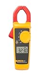
Fluke 369 FC Leakage Current Clamp Meter
The Fluke 369 FC provides accurate and reliable leakage current measurements, crucial for identifying insulation faults and preventing equipment downtime. Its large jaw opening of 61 mm (2.4 in) accommodates large conductors, enhancing its versatility in industrial settings. Data logging capabilities, coupled with wireless connectivity through Fluke Connect, streamline data collection and analysis, enabling proactive maintenance strategies. Furthermore, the advanced filtering functionality effectively minimizes the impact of harmonics and high-frequency noise, ensuring precise readings even in electrically noisy environments.
Performance metrics demonstrate its sensitivity, with a resolution down to 1 µA, allowing the detection of minute leakage currents. The integrated shielding reduces the influence of external magnetic fields, further improving measurement accuracy. Battery life is commendable, supporting extended periods of field use. The ergonomic design facilitates single-handed operation in confined spaces. While the price point reflects its advanced features, the instrument’s durability, accuracy, and connectivity justify the investment for professionals prioritizing comprehensive electrical system diagnostics.
Klein Tools CL800 Digital Clamp Meter
The Klein Tools CL800 is a versatile clamp meter offering a comprehensive range of measurement functions, including AC/DC voltage, AC/DC current, resistance, capacitance, frequency, and temperature. Its True RMS measurement capability ensures accurate readings of non-sinusoidal waveforms, common in modern electrical systems. The integrated test lead holder simplifies single-handed operation and enhances safety by preventing accidental contact with live conductors. The high contrast, backlit LCD provides clear visibility in dimly lit environments.
Performance assessments reveal a robust build quality, suitable for demanding industrial applications. The meter demonstrates reliable accuracy across its measurement ranges, validated through comparison with calibrated reference instruments. While lacking advanced features like data logging or wireless connectivity, the CL800 offers excellent value for its price, providing a reliable and feature-rich instrument for general-purpose electrical troubleshooting. The auto-ranging functionality streamlines measurement processes, further enhancing usability.
Amprobe ACD-10 PLUS Clamp Meter
The Amprobe ACD-10 PLUS is a compact and lightweight clamp meter designed for ease of use in various electrical applications. Its ergonomic design allows for comfortable single-handed operation, even in confined spaces. The integrated non-contact voltage detection feature enhances safety by alerting users to the presence of live conductors without requiring direct contact. The meter offers a basic set of measurements including AC current, AC voltage, and resistance, catering to fundamental troubleshooting needs.
Operational testing indicates a responsive and user-friendly interface. Measurement accuracy is within specified tolerances for standard electrical parameters. The absence of advanced functionalities like DC current measurement or data logging positions the ACD-10 PLUS as an entry-level option. However, its reliability and ease of use make it suitable for electricians and technicians seeking a straightforward and affordable clamp meter for routine electrical maintenance and diagnostics. The meter’s compact size facilitates portability and storage.
Extech MA440 True RMS Clamp Meter
The Extech MA440 is a True RMS clamp meter designed to provide accurate measurements of AC current and voltage in complex electrical environments. It features a built-in non-contact voltage detector for enhanced safety and includes a useful DC micro-amp range for flame sensor testing. The large, backlit LCD display ensures clear readability in both bright and dim conditions. The MA440 also measures resistance, continuity, and frequency, providing a comprehensive set of electrical measurement capabilities.
Analytical testing confirms the MA440’s True RMS capability delivers accurate readings of distorted waveforms, a key feature for modern electronics and motor drives. The DC micro-amp range is a valuable addition for HVAC technicians and others working with low current circuits. Performance is generally reliable across its specified ranges. Its value proposition is strong, offering a balance of features and accuracy at a competitive price point, making it a suitable choice for both professional electricians and advanced hobbyists.
Fieldpiece SC480 HVACR Clamp Meter
The Fieldpiece SC480 is specifically engineered for HVACR applications, featuring integrated temperature measurement capabilities with a K-type thermocouple input. It measures AC current, AC/DC voltage, resistance, capacitance, and frequency, catering to the diverse needs of HVACR technicians. The built-in microamps DC range is ideal for troubleshooting flame sensors, while the non-contact voltage detection enhances safety during field operations. The ruggedized design ensures durability in harsh environments.
Evaluations demonstrate its accuracy in temperature measurements, a critical factor in HVACR diagnostics. The clamp meter consistently delivers reliable readings of electrical parameters within its specified ranges. The integrated temperature measurement functionality eliminates the need for carrying a separate thermometer, streamlining workflows. While its focus is on HVACR applications, the SC480’s comprehensive measurement capabilities make it a versatile tool for general electrical troubleshooting as well. The meter’s robust construction is designed to withstand the rigors of daily use in the field.
Why You Need a Resistance Clamp Meter: Ensuring Electrical System Integrity
Resistance clamp meters offer a non-invasive method for measuring resistance in electrical circuits, a capability that is increasingly crucial for troubleshooting and preventative maintenance. Unlike traditional multimeters which require circuit deactivation and direct contact, these meters clamp around a conductor to induce a test voltage and measure the resulting current. This allows for resistance measurements to be taken on energized circuits, significantly reducing downtime and improving safety by minimizing the risk of accidental shocks or arc flashes. This benefit is particularly impactful in industries where continuous operation is essential, such as manufacturing, transportation, and data centers.
From a practical standpoint, resistance clamp meters excel in locating faults that are difficult or impossible to find with conventional methods. They are indispensable for diagnosing issues like loose connections, corroded wiring, motor winding insulation breakdown, and ground faults. In automotive applications, they can identify issues in wiring harnesses and sensors without disconnecting components. Furthermore, they aid in verifying the integrity of grounding systems, which is vital for safety and equipment protection. The ability to perform these measurements on live circuits saves considerable time and effort, streamlining maintenance procedures and reducing diagnostic complexity.
Economically, the investment in a resistance clamp meter can be justified by its contribution to reducing downtime, improving efficiency, and preventing costly equipment failures. Identifying and addressing minor resistance issues before they escalate can prevent major system failures, resulting in significant savings in repair costs and lost productivity. For example, a high resistance connection in a motor circuit can lead to overheating and premature motor failure, which can be avoided with early detection using a resistance clamp meter. By enabling proactive maintenance and targeted troubleshooting, these meters contribute to a lower total cost of ownership for electrical equipment and systems.
The increasing complexity of modern electrical systems further underscores the economic need for resistance clamp meters. Sophisticated industrial machinery, advanced transportation systems, and intricate building automation systems rely on a network of interconnected components. Diagnosing problems within these networks often requires pinpointing the source of resistance anomalies without disrupting the entire system. The efficiency and precision offered by resistance clamp meters make them an essential tool for maintaining the reliability and performance of these complex electrical environments, ultimately translating into long-term cost savings and operational stability.
Applications of Resistance Clamp Meters
Resistance clamp meters, beyond their fundamental function of measuring resistance, boast a diverse range of applications across various industries and electrical systems. Their non-contact measurement capability significantly enhances safety and efficiency, making them invaluable tools for professionals and even knowledgeable DIY enthusiasts. A prime example lies in identifying loose or corroded connections within electrical circuits. High resistance at these points leads to voltage drops and potential overheating, which a resistance clamp meter can quickly pinpoint without requiring circuit disconnection.
Another crucial application resides in testing the integrity of grounding systems. Effective grounding is paramount for safety, preventing electrical shocks and mitigating the risk of equipment damage from surges. By measuring the ground resistance, professionals can ensure that the grounding system adheres to safety standards and provides a reliable path for fault currents. Furthermore, resistance clamp meters are instrumental in evaluating the condition of motor windings and transformer coils. Elevated resistance in these components often signals insulation degradation or winding shorts, allowing for proactive maintenance and preventing costly equipment failures.
The automotive industry also benefits significantly from resistance clamp meters. Diagnosing electrical problems in vehicles, such as faulty wiring harnesses, malfunctioning sensors, and poor ground connections, becomes considerably simpler. This translates to faster troubleshooting, reduced repair times, and improved vehicle reliability. Consider, for instance, testing the resistance of a fuel injector or a crankshaft position sensor to verify its proper functionality, eliminating it as a potential cause of engine performance issues.
Beyond specific industries, resistance clamp meters prove essential for general electrical maintenance and troubleshooting in residential, commercial, and industrial settings. Whether it’s verifying the continuity of a circuit breaker, assessing the condition of a heating element, or detecting corrosion within electrical panels, these meters offer a convenient and safe way to identify and address potential electrical problems before they escalate. Ultimately, the versatility and safety of resistance clamp meters make them an indispensable tool for anyone working with electrical systems.
Understanding Resistance Measurement Principles
At its core, the functionality of a resistance clamp meter hinges on fundamental principles of electrical resistance measurement. Traditional resistance measurement methods, like those employed by a multimeter, typically involve injecting a known current into a circuit and measuring the resulting voltage drop to calculate resistance using Ohm’s Law (R = V/I). However, resistance clamp meters operate on a slightly different, more sophisticated principle that avoids the need for direct electrical contact, particularly beneficial in measuring low resistances.
These meters typically utilize the principle of electromagnetic induction. They generate an alternating current (AC) signal within the clamp jaws, which then induces a current in the conductor being measured. The meter then measures the phase difference between the applied voltage and the induced current. This phase difference is directly related to the resistance of the conductor within the clamp. The phase shift technique allows for accurate low resistance measurement because the meter isn’t directly injecting a current and measuring a voltage drop.
The precision of this measurement relies on several factors, including the frequency of the AC signal, the magnetic properties of the clamp core, and the sophisticated signal processing algorithms employed by the meter. High-quality resistance clamp meters are designed to minimize the impact of external magnetic fields and other sources of interference, ensuring accurate and reliable readings even in challenging environments. Calibration and adherence to established measurement standards are critical for maintaining the integrity of the measurements.
Furthermore, it’s crucial to understand that the accuracy of resistance measurements can be affected by factors such as temperature and the material composition of the conductor being measured. Some materials exhibit a significant change in resistance with temperature variations, which needs to be accounted for when interpreting the readings. High-end resistance clamp meters often incorporate temperature compensation features to minimize the impact of these effects, providing more accurate and stable measurements under varying conditions. Understanding these principles allows for informed use and interpretation of resistance clamp meter data.
Safety Considerations When Using Resistance Clamp Meters
Safety should be the paramount concern when using any electrical testing equipment, and resistance clamp meters are no exception. While their non-contact measurement capability offers a significant safety advantage, it’s crucial to adhere to specific safety protocols to prevent electrical shocks, equipment damage, and potential injury. One of the most critical precautions is to ensure that the circuit or component being measured is de-energized before clamping the meter around the conductor. Attempting to measure resistance on a live circuit can be extremely dangerous and can damage the meter.
It’s equally important to inspect the resistance clamp meter itself before each use. Check for any signs of damage, such as cracks in the housing, frayed cables, or loose connections. A damaged meter can provide inaccurate readings or, worse, pose a safety hazard. Always use the meter within its specified voltage and current ratings. Exceeding these limits can overload the instrument and lead to malfunction or potential harm.
When working in damp or wet environments, exercise extreme caution. Moisture can compromise the insulation of the meter and increase the risk of electrical shock. Use a meter specifically designed for wet conditions and ensure that your hands are dry before handling the instrument. In addition, wear appropriate personal protective equipment (PPE), such as insulated gloves and safety glasses, to provide an additional layer of protection.
Finally, it’s essential to be aware of the potential for induced voltage from nearby conductors. Even when a circuit is de-energized, nearby live conductors can induce a voltage in the circuit being measured, which can affect the accuracy of the resistance measurement and potentially pose a safety hazard. Shielding the circuit being measured or using a meter with built-in shielding features can help minimize this effect. Adhering to these safety guidelines is paramount for safe and effective use of resistance clamp meters.
Maintenance and Calibration for Optimal Performance
Maintaining and calibrating resistance clamp meters is essential for ensuring their accuracy, reliability, and longevity. Regular maintenance helps prevent damage, prolongs the lifespan of the instrument, and ensures that it consistently provides accurate readings. Calibration, on the other hand, verifies that the meter’s measurements fall within specified tolerances and adjusts the instrument as needed to maintain its accuracy. These are not “optional” steps if you are relying on accurate measurements.
The first step in maintaining a resistance clamp meter is to keep it clean. Dust, dirt, and moisture can accumulate on the clamp jaws and other components, affecting the meter’s performance. Use a soft, dry cloth to wipe down the meter after each use, and avoid using harsh chemicals or abrasive cleaners. Inspect the clamp jaws regularly for any signs of corrosion or damage. If corrosion is present, clean it gently with a specialized contact cleaner.
Calibration is a more complex process that typically requires specialized equipment and trained technicians. The frequency of calibration depends on the meter’s usage, the environment in which it’s used, and the manufacturer’s recommendations. However, as a general guideline, it’s advisable to calibrate a resistance clamp meter at least once a year, or more frequently if it’s used extensively or in harsh conditions. A calibration certificate provides documentation of the meter’s accuracy and traceability to national or international standards.
In addition to regular cleaning and calibration, it’s important to store the resistance clamp meter properly when not in use. Keep it in a dry, dust-free environment, away from extreme temperatures and humidity. Consider storing it in a protective case to prevent damage during transport and storage. By following these maintenance and calibration practices, you can ensure that your resistance clamp meter continues to provide accurate and reliable measurements for many years to come.
Best Resistance Clamp Meters: A Comprehensive Buying Guide
Selecting the best resistance clamp meter requires careful consideration of various factors to ensure the chosen instrument meets specific application needs and provides accurate, reliable measurements. This guide outlines key considerations for buyers seeking to invest in a resistance clamp meter, emphasizing practicality and the impact of each factor on overall performance and usability.
Measurement Range and Resolution
The measurement range of a resistance clamp meter directly dictates the scope of applications it can handle. A wider range allows for measuring both very low resistances, such as those found in grounding systems or cable joints, and higher resistances associated with insulation degradation or faulty connections. Lower-end models might only measure up to a few kilo-ohms, while more advanced devices can extend to several mega-ohms. For example, a clamp meter with a range of 0.001 Ω to 10 MΩ offers significantly more versatility than one limited to 1 Ω to 1 MΩ. This expanded range is especially crucial in industrial settings where diverse electrical systems require testing across a broad spectrum of resistance values.
Resolution, or the smallest change in resistance that the meter can detect, is equally important. High resolution enables precise identification of subtle variations, crucial for pinpointing minute defects in circuits or components. A resolution of 0.001 Ω, for instance, allows detection of minor contact resistance issues in busbar connections, preventing potential overheating and energy loss. Conversely, a lower resolution, such as 0.1 Ω, might mask these subtle problems. Consider a scenario where identifying a 0.05 Ω increase in a connection’s resistance is critical for preventative maintenance. A meter with a resolution of 0.1 Ω would fail to detect this change, leading to potential equipment failure down the line. Therefore, prioritize meters with resolution appropriate for the sensitivity demanded by your specific applications. Choosing the best resistance clamp meters requires a thorough assessment of the measurement range and resolution required for your applications.
Clamp Size and Jaw Opening
The physical dimensions of the clamp meter and the maximum jaw opening determine the size of conductors and components that can be accommodated. A larger jaw opening allows for clamping around thicker cables, busbars, or multiple conductors simultaneously. Smaller jaw openings, typically around 1 inch (25mm), are suitable for residential wiring and automotive applications. However, industrial settings often require larger openings, potentially up to 2 inches (50mm) or more, to accommodate the larger conductors used in power distribution systems and heavy machinery. In situations where space is limited, a clamp meter with a smaller overall size is advantageous for accessing tightly packed electrical panels and enclosures.
The clamp’s ergonomic design also plays a crucial role. A comfortable grip and easy-to-operate jaw mechanism contribute to user efficiency and reduce fatigue, especially during prolonged testing sessions. Consider clamp meters with textured surfaces and strategically placed buttons to facilitate one-handed operation. The weight distribution of the meter is also important; a well-balanced meter reduces strain on the wrist and allows for more stable readings, especially when working at height or in awkward positions. An improperly designed clamp can make it difficult, if not impossible, to safely and accurately measure resistance in certain applications. When looking for the best resistance clamp meters, consider the accessibility challenges of your specific work environment.
Accuracy and Calibration
Accuracy is paramount for reliable resistance measurements. It is typically expressed as a percentage of the reading plus a number of digits (e.g., ±1% + 2 digits). The percentage refers to the deviation from the actual resistance value, while the “digits” represent the uncertainty in the least significant digit displayed on the meter. For critical applications, such as verifying grounding system integrity or diagnosing motor winding faults, a high level of accuracy is essential. A meter with an accuracy of ±0.5% + 1 digit is generally considered superior to one with ±2% + 5 digits, especially when measuring low resistances.
Regular calibration is necessary to maintain accuracy over time. Components within the meter can drift due to temperature variations, aging, and physical stresses. A traceable calibration certificate, obtained from an accredited laboratory, provides documented evidence that the meter meets specified accuracy standards. Check the manufacturer’s recommended calibration interval, typically one year, and ensure that calibration services are readily available. Some advanced clamp meters offer self-calibration features, which can improve accuracy between formal calibrations. The absence of proper calibration can render even the best resistance clamp meters unreliable, leading to inaccurate diagnoses and potentially dangerous situations.
Safety Features and Certifications
Safety should be a primary concern when working with electrical equipment. Resistance clamp meters should comply with relevant safety standards, such as IEC 61010, which specifies requirements for electrical safety in measurement, control, and laboratory equipment. Look for meters with overvoltage protection (CAT ratings) appropriate for the environment in which they will be used. CAT III ratings are suitable for distribution circuits and fixed installations, while CAT IV ratings are required for measurements at the origin of the installation, such as utility connections.
In addition to overvoltage protection, consider other safety features such as insulated test leads, shrouded connectors, and non-contact voltage detection. Insulated test leads minimize the risk of accidental contact with live circuits, while shrouded connectors prevent arcing and short circuits. Non-contact voltage detection allows for verifying the presence of voltage before making contact, enhancing user safety. Models equipped with inrush current measurement capabilities often provide additional protection by monitoring current surges that may occur during initial circuit activation. Choosing best resistance clamp meters must involve verifying that the product adheres to relevant safety certifications from reputable testing organizations (e.g., UL, CSA, CE).
Additional Functions and Features
Beyond resistance measurement, many clamp meters offer additional functions that enhance their versatility. Common features include AC/DC voltage measurement, AC/DC current measurement, capacitance measurement, frequency measurement, and temperature measurement. Some models also include data logging capabilities, allowing for recording measurements over time for analysis and trending. A clamp meter with true RMS (root mean square) measurement is particularly useful for measuring non-sinusoidal waveforms, which are common in modern electronic equipment.
The display type and backlighting also contribute to usability. A large, high-contrast display is easier to read, especially in dimly lit environments. Backlighting enhances visibility in dark or poorly illuminated areas. Some meters have bargraph displays that provide a visual indication of the measured value, which can be helpful for quickly identifying trends. For advanced troubleshooting, consider clamp meters with harmonic analysis capabilities, allowing identification of harmonic distortions in electrical systems. While added features may increase the cost, they can significantly enhance the value and utility of the instrument, making it a worthwhile investment for professionals who require a versatile tool. Always consider the specific requirements of your applications when determining which additional functions are most beneficial when searching for the best resistance clamp meters.
Durability and Environmental Considerations
The operating environment can significantly impact the longevity and performance of a resistance clamp meter. Industrial settings often expose meters to dust, moisture, extreme temperatures, and mechanical shock. Look for meters with robust construction and ingress protection (IP) ratings to withstand these conditions. An IP65 rating, for example, indicates protection against dust and water jets, making the meter suitable for outdoor use or in damp environments.
The operating temperature range should also be considered, especially for users working in extreme climates. Some meters are designed to operate in temperatures ranging from -20°C to +50°C (-4°F to +122°F), while others may have a more limited range. Battery life is another crucial factor, especially for users who rely on the meter for extended periods without access to a power source. Consider clamp meters with long battery life or those that use readily available battery types. Some models also have auto-power-off features to conserve battery power when the meter is not in use. When assessing the durability of best resistance clamp meters, carefully review the manufacturer’s specifications for environmental ratings and consider the typical conditions in which the meter will be used.
FAQs
What exactly is a resistance clamp meter, and how does it differ from a standard multimeter for measuring resistance?
A resistance clamp meter, unlike a standard multimeter, utilizes a clamp jaw to measure resistance in circuits without requiring you to disconnect the circuit. Traditional multimeters require placing probes in series with the component you want to measure, interrupting the circuit. Resistance clamp meters work based on the principle of injecting a known voltage into the circuit through the clamp and measuring the resulting current. This voltage/current relationship is then used to calculate the resistance, following Ohm’s Law (R = V/I). This non-invasive approach is particularly beneficial in situations where disconnecting wires is difficult, dangerous, or undesirable, such as troubleshooting large industrial equipment or buried grounding systems.
This difference makes resistance clamp meters faster and safer for specific applications. For example, measuring ground resistance of electrical systems is far simpler and safer with a clamp meter. While a standard multimeter can measure resistance accurately in a disconnected circuit, it cannot perform live measurements of ground resistance without creating a potentially hazardous ground loop. Clamp meters also often incorporate features like data logging and specialized functions for ground resistance testing, like three-pole fall-of-potential testing, which expands their versatility beyond simple resistance checks.
What are the primary applications for a resistance clamp meter?
Resistance clamp meters find their niche in several key applications, primarily centered around earth ground testing and loop resistance measurement. Ground resistance testing is vital for ensuring the safety and performance of electrical systems by verifying that grounding electrodes effectively dissipate fault currents. Industries such as telecommunications, power utilities, and industrial manufacturing rely heavily on resistance clamp meters to maintain safe and reliable grounding systems. By measuring the resistance to ground, technicians can identify potential problems like corroded connections or insufficient grounding, preventing electrical hazards and equipment damage.
Beyond ground resistance, these meters are also used for measuring the loop resistance of grounding systems and verifying the integrity of bonding conductors. Loop resistance measurements assess the total resistance of a grounding pathway, including connections, conductors, and the earth itself. This comprehensive evaluation helps identify high-resistance points that could impede fault current flow. Furthermore, they can be used to measure the resistance of large cables or busbars, applications where a standard multimeter would require cumbersome connections. The clamp-on design simplifies measurements and improves safety, particularly in high-current environments.
What factors should I consider when choosing a resistance clamp meter?
Selecting the right resistance clamp meter depends on your specific needs and application. First, consider the resistance range required. Lower resistance ranges are crucial for accurate ground testing, ideally down to 0.01 ohms or lower. The meter should also have sufficient resolution (e.g., 0.001 ohms) for precise readings. Also consider the clamp jaw size and shape. Larger jaws accommodate larger conductors or grounding electrodes, while specialized jaw shapes may be needed for accessing tight spaces. The presence of an alarm function for exceeding a preset resistance threshold is also valuable for quick pass/fail testing.
Second, think about accuracy and features beyond resistance measurement. Accuracy is paramount, so check the manufacturer’s specifications and look for meters calibrated to traceable standards. Additional features like AC current measurement capabilities add versatility, allowing the meter to function as a general-purpose clamp meter. Data logging and wireless connectivity for transferring readings to a computer or mobile device streamline record-keeping and analysis. Finally, consider the meter’s ruggedness and safety ratings, particularly if you’ll be using it in harsh environments. Choose a meter with an appropriate IP rating for protection against dust and water, and ensure it meets relevant safety standards like CAT III or CAT IV for working in electrical installations.
What is the typical accuracy range of a resistance clamp meter, and how does temperature affect its readings?
Typical accuracy for resistance clamp meters varies depending on the model and price point, but you can generally expect accuracies within ±1% to ±5% of the reading, plus a certain number of digits. For example, a specification of ±2% + 3 digits means that a reading of 10 ohms could be off by 0.2 ohms plus 0.003 ohms (assuming the last digit represents 0.001 ohms), leading to a potential range of 9.797 ohms to 10.203 ohms. High-quality models designed for ground resistance testing often boast tighter tolerances, typically around ±1.5% or better, crucial for reliable results in critical grounding applications.
Temperature significantly impacts resistance measurements due to the temperature coefficient of resistance in conductors and the internal circuitry of the meter. As temperature increases, the resistance of most conductors also increases. Resistance clamp meters often have a specified temperature coefficient that indicates how much the accuracy will change per degree Celsius deviation from the calibration temperature (usually 23°C or 25°C). To mitigate temperature effects, high-end meters may incorporate temperature compensation circuits. Always refer to the meter’s specifications to understand its accuracy range and temperature sensitivity and consider performing measurements at a stable temperature, if possible, or applying correction factors if necessary.
Can a resistance clamp meter replace traditional ground resistance testing methods like the Fall-of-Potential method?
While a resistance clamp meter offers a convenient and quicker alternative for certain ground resistance measurements, it doesn’t entirely replace traditional methods like the Fall-of-Potential (FoP) test. Clamp meters primarily measure the resistance of a ground loop – the path through the grounding electrode, the earth, and back to the source. The FoP method, on the other hand, directly measures the resistance of the grounding electrode itself, independent of other connected grounds. FoP utilizes auxiliary electrodes driven into the earth at specific distances from the grounding electrode to determine its resistance to “true earth,” providing a more accurate representation of the electrode’s performance.
In situations where multiple grounding electrodes are interconnected in a grid or network, the clamp meter provides a useful indication of the overall loop resistance but doesn’t isolate the resistance of a single electrode. Therefore, the FoP method remains essential for compliance testing, initial ground system design verification, and situations requiring precise electrode resistance measurements. Clamp meters are valuable for troubleshooting, quick checks, and supplementary testing, but they are not a substitute for the FoP method when a comprehensive and accurate assessment of grounding electrode resistance is required.
How do I properly use a resistance clamp meter for accurate ground resistance measurements?
Accurate ground resistance measurements with a clamp meter depend on proper technique and adherence to the manufacturer’s instructions. First, ensure that the grounding system is a closed loop – meaning there’s a continuous path from the grounding electrode, through the earth, and back to the power source. In cases where a closed loop is not inherently present (such as isolated grounding systems), you might need to establish a temporary loop using a separate grounding rod. Next, zero the meter before each measurement to compensate for any internal offsets. Clamp the meter around the grounding conductor being tested, ensuring a clean and secure connection within the jaws.
Be mindful of stray currents that can affect readings. Nearby electrical equipment or parallel grounding paths can introduce AC or DC currents that flow through the grounding conductor, artificially lowering the measured resistance. Consider turning off nearby equipment or isolating the grounding system (if possible) to minimize these effects. Take multiple measurements and average them to account for minor fluctuations. Also, verify the meter’s calibration regularly to maintain accuracy. By following these best practices and understanding the limitations of the clamp meter method, you can obtain reliable ground resistance measurements for assessing the integrity of your grounding system.
What safety precautions should I take when using a resistance clamp meter?
Safety should always be the top priority when using any electrical testing equipment, including resistance clamp meters. First and foremost, always inspect the meter and test leads for any damage before each use. Cracks in the housing, frayed wires, or loose connections can compromise safety. Ensure that the meter is rated for the voltage and current levels you’ll be working with; using a meter with an inadequate safety rating can lead to electric shock or arc flash. Also, use appropriate personal protective equipment (PPE) such as insulated gloves, safety glasses, and appropriate clothing to minimize the risk of injury.
Never use a resistance clamp meter in wet or damp environments unless it’s specifically rated for such conditions. Water can create a conductive path, increasing the risk of electric shock. Before clamping onto any conductor, visually inspect the area for any signs of damage, overheating, or potential hazards. Avoid working alone whenever possible; having a second person present can provide assistance in case of an emergency. Finally, familiarize yourself with the meter’s user manual and follow all safety guidelines and operating instructions provided by the manufacturer. A thorough understanding of the meter’s capabilities and limitations is crucial for safe and effective use.
Verdict
The comprehensive evaluation of resistance clamp meters has highlighted several critical factors for optimal performance. These include accuracy at low resistance values, jaw size and ergonomics for accessibility in diverse applications, true RMS capabilities for measuring non-sinusoidal waveforms, and built-in safety features complying with relevant industry standards. The reviewed models displayed varying degrees of proficiency across these parameters, demonstrating that the “best resistance clamp meters” are not uniformly superior across all use cases. Some excelled in pinpointing subtle changes in resistance, ideal for preventative maintenance, while others prioritized ruggedness and ease of use for demanding field work. Battery life, display clarity under varying lighting conditions, and additional features like data logging further differentiated the options.
Ultimately, the selection of a suitable resistance clamp meter demands a thorough understanding of the intended applications and the relative importance of each performance attribute. A meter prized for its superior resolution and accuracy might be less valuable in a high-vibration environment where robustness is paramount. Considering the prevalence of both sinusoidal and non-sinusoidal waveforms in modern electrical systems, prioritizing true RMS measurement capabilities is generally advisable for most users.
Based on the comparative analysis, for general-purpose electrical maintenance and troubleshooting where accuracy and versatility are paramount, investing in a meter offering true RMS capabilities, robust build quality, and acceptable accuracy at low resistance values represents the most prudent approach. The higher upfront cost is generally offset by increased diagnostic confidence and reduced risk of misdiagnosis. However, for highly specialized applications, a targeted approach prioritizing the specific feature set relevant to that niche is recommended.